English
 русский
 Español
Content
- 1 The Role of the Inner Ball Joint in Automotive Steering Systems
- 2 Inner Tie Rod Ball Joint vs. Outer Tie Rod End: Understanding the Difference
- 3 Li Auto L6 Inner Ball Joint: Platform-Specific Requirements and Specification
- 4 Diagnosing Inner Ball Joint Wear: Symptoms and Inspection Methods
- 5 Replacement Procedure and Post-Installation Requirements
The Role of the Inner Ball Joint in Automotive Steering Systems
The automotive inner ball joint is one of the most mechanically demanding components in a vehicle's steering linkage. Positioned between the steering rack and the outer tie rod end, it forms the pivot point that allows the steering rack's linear motion to be translated into the angular movement required to turn the front wheels. Unlike the outer tie rod end — which connects to the wheel hub carrier and is directly exposed to road impacts — the inner ball joint operates under a different but equally significant stress regime: it must accommodate the full steering effort generated by the rack while simultaneously handling the suspension articulation that occurs as the wheel moves up and down over road surfaces.
On modern vehicles, including extended-range electric platforms like the Li Auto L6, the steering system is electronically assisted (EPS), which means the rack generates precise, high-frequency force inputs that pass directly through the inner ball joint on every steering correction. The inner joint must transmit these forces without play, vibration, or energy loss, while maintaining consistent articulation across a temperature range that can span from −30°C in winter cold starts to over 80°C under sustained urban driving with repeated steering inputs. This combination of precision, force transmission, and thermal resilience defines what a well-engineered automotive inner ball joint must deliver in service.
Inner Tie Rod Ball Joint vs. Outer Tie Rod End: Understanding the Difference
The inner tie rod ball joint is frequently confused with the outer tie rod end in service documentation and parts catalogs, but the two components perform different functions and fail through different mechanisms. Understanding the distinction is essential for accurate diagnosis and correct parts ordering.
| Parameter | Inner Tie Rod Ball Joint | Outer Tie Rod End |
|---|---|---|
| Location | Rack end, behind steering boot | Wheel hub carrier, exposed |
| Primary motion | Rotational + axial under rack force | Angular articulation at wheel |
| Typical failure mode | Axial play, torn boot, grease loss | Radial looseness, stud wear |
| Symptom when worn | Steering wander, vague on-center feel | Clunk over bumps, uneven tire wear |
| Wheel alignment effect | Toe instability under braking | Direct toe change, pull to one side |
| Service access | Requires boot removal, inner rod tool | Standard socket and puller |
The inner tie rod ball joint is protected by the steering rack boot, which keeps road contamination away from the joint's grease-packed ball socket. When the boot tears or splits — a common occurrence on vehicles with high mileage or exposure to road salt — grit and water enter the joint housing, accelerating wear of the ball socket liner. At this point, axial play develops in the joint: the ball can move longitudinally within its housing rather than pivoting cleanly, introducing a dead zone into the steering response that the driver perceives as vagueness or wandering, particularly at highway speeds where small corrections are continuously required.
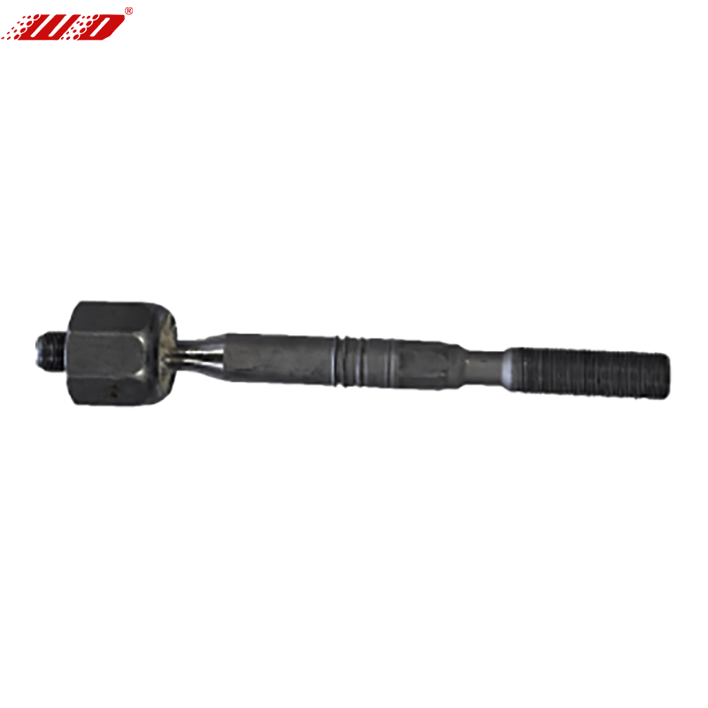
Li Auto L6 Inner Ball Joint: Platform-Specific Requirements and Specification
The Li Auto L6 inner ball joint operates within a steering architecture that reflects the specific demands of a large extended-range SUV platform. The L6 is built on Li Auto's second-generation extended-range platform, with a front axle load capacity exceeding 1,100 kg per side when fully loaded with passengers and cargo. The steering system uses an EPS rack calibrated for the vehicle's 2,920 mm wheelbase and its tendency toward understeer bias at the handling limit — characteristics that place consistent, defined demands on the inner ball joint throughout the vehicle's service life.
The X04-NQT inner ball joint engineered for this application has the following verified specifications:
- Dimensions: 200 × 130 × 80 mm — an envelope sized to fit within the L6's steering rack housing geometry without modification to adjacent brackets or boot clamp positions.
- Weight: 0.7 kg per unit — consistent with the use of a forged steel ball stud and a reinforced polymer socket liner housed in an aluminum alloy body, balancing unsprung mass considerations with the structural requirements of the application.
- Thread specification: Matched to the Li Auto L6 rack thread pitch and torque specification to ensure secure assembly without risk of cross-threading during installation.
- Articulation angle: Designed to accommodate the full suspension travel range of the L6's front MacPherson strut setup, including extreme jounce and rebound positions, without binding or transmitting load through the boot rather than the ball socket.
- Grease specification: Pre-packed with high-temperature lithium complex grease rated for continuous service above 150°C, addressing the thermal environment near the front differential and EPS motor on the L6 platform.
For Li Auto L6 inner ball joint replacement, confirming that the replacement part matches all five of these parameters — not just the thread dimensions — is critical to maintaining the OEM steering feel and preventing premature failure of the new component.
Diagnosing Inner Ball Joint Wear: Symptoms and Inspection Methods
Inner ball joint wear develops gradually and its early symptoms are easy to misattribute to other steering or suspension components. Accurate diagnosis before ordering replacement parts prevents unnecessary work and ensures the correct component is addressed. The following symptoms indicate automotive inner ball joint wear and warrant inspection:
- Steering wander at highway speed: The vehicle requires continuous minor corrections to maintain a straight line, even on a flat, cambered road. This symptom reflects axial play in one or both inner joints allowing toe angle to shift under aerodynamic and road surface loads.
- Vague on-center steering feel: A dead zone of approximately 5–15 degrees of steering wheel rotation around the straight-ahead position where no directional change occurs. This is the clearest indication of inner joint play in an EPS-equipped vehicle where rack friction is otherwise minimal.
- Toe instability under braking: The vehicle pulls to one side during moderate to heavy braking. Braking forces load the steering linkage longitudinally; a worn inner joint with axial play allows the rack to shift slightly, changing toe angle asymmetrically and producing the pull.
- Visible boot damage: A split, cracked, or oil-contaminated steering rack boot is both a symptom of potential inner joint contamination and a precursor to accelerated wear. Any boot damage should trigger inner joint inspection regardless of whether steering symptoms are yet present.
- Clunking from the steering rack area: An audible knock when transitioning from left to right steering lock at low speed, particularly on uneven surfaces, indicates that axial play has progressed to the point where the ball is impacting the limits of its socket travel.
Physical inspection requires removing the steering boot to access the inner joint directly. With the vehicle on a lift and the front wheels hanging free, grasp the inner tie rod and attempt to move it axially — along the axis of the rack. Any perceptible movement beyond 0.5 mm indicates wear that exceeds the serviceable limit. Rotational stiffness should be uniform throughout the articulation range; any roughness, binding, or free rotation indicates socket liner wear or contamination and requires replacement.
Replacement Procedure and Post-Installation Requirements
Replacing the inner tie rod ball joint is a straightforward procedure when approached with the correct tooling, but errors in torque specification or boot installation consistently produce premature failure of the new component. The following sequence applies to the Li Auto L6 and most rack-and-pinion equipped vehicles with accessible inner tie rod joints.
Pre-Removal Steps
Photograph or measure the outer tie rod end position relative to the inner rod thread before disassembly. This preserves the approximate toe setting and reduces the alignment correction required after reassembly. Count and record the number of exposed threads on the outer rod end as a reference for reinstallation.
Removal and Installation
Slide the steering boot toward the rack center to expose the inner joint. Use a dedicated inner tie rod removal tool — a crow-foot or spanner type that engages the flats on the inner joint body — to unscrew the joint from the rack end. Do not use pipe wrenches or adjustable pliers, which deform the joint housing and risk damaging the rack thread. Install the new X04-NQT Li Auto L6 inner ball joint by hand until fully seated, then torque to the manufacturer's specification using the inner rod tool and a torque wrench extension. Reposition the steering boot over the new joint, confirm the boot clamps are correctly seated in the grooves on both the rack housing and the inner rod body, and install new clamps rather than reusing the originals.
Post-Installation Wheel Alignment
Wheel alignment — specifically front toe — must be measured and adjusted after any automotive inner ball joint replacement, even when the outer rod end position has been carefully preserved. The new joint's slightly different assembled length, combined with any variation in thread engagement depth, will shift toe by a measurable amount. On the Li Auto L6, the front toe specification is tight by SUV standards to support the vehicle's highway stability calibration; operating outside this specification accelerates front tire wear and degrades the straight-line stability that the inner ball joint's precision is designed to support.