 English
 русский
 Español
The Li Auto L6 front axle is a load-bearing, steering, and in certain configurations, a driving assembly that integrates the suspension struts, steering knuckles, constant velocity drive shafts, wheel bearings, and the subframe into a single coordinated system. Its primary function is to maintain precise wheel alignment under the variable loads imposed by braking, cornering, and the vehicle's substantial curb weight, which exceeds 2,300 kg. Unlike a simple beam axle that connects two wheels rigidly, the L6 employs an independent suspension design at the front, allowing each wheel to react to road imperfections without transferring the disturbance to the opposite side. This design is essential for preserving the steering precision and ride composure expected of a modern luxury SUV.
The most common indicator of a front axle issue is not a catastrophic failure, but a gradual degradation of noise and feel. A worn front wheel bearing announces itself as a low-frequency hum that intensifies between 40 and 80 km/h and changes pitch when the steering wheel is turned slightly to load or unload the bearing. A failing constant velocity joint, by contrast, produces a rhythmic clicking sound during tight turns, particularly when maneuvering in a parking lot at full steering lock. These symptoms are diagnostic signatures that allow an attentive owner to identify the failing component before it compromises safety. Addressing these early warnings is critical because a seized wheel bearing or a separated drive shaft at highway speed converts a repairable maintenance item into a potential loss of vehicle control.
Content
Suspension Architecture and Steering Knuckle Design
The Li Auto L6 front suspension utilizes a MacPherson strut or double-wishbone layout, depending on the specific trim and model year. In either configuration, the steering knuckle—the cast or forged component that carries the wheel hub, brake caliper, and suspension links—is the structural heart of the front axle assembly. This knuckle is typically manufactured from ductile cast iron or forged aluminum alloy, selected for its ability to withstand the bending and torsional forces generated during emergency braking, where the load on the front axle can momentarily exceed 1.5 times the static weight of the vehicle's front end.
The steering knuckle interfaces with the strut via a clamp bracket secured by two high-tensile bolts torqued to a precise specification, commonly 120 to 160 Nm plus an additional angle torque of 90 degrees. Any deviation from this torque value during reassembly, whether from an impact wrench used without a torque wrench or from reusing torque-to-yield bolts that have already been stretched, will result in a loose strut-to-knuckle connection. This looseness manifests as an audible clunk over bumps and, over time, accelerated wear of the strut mounting hole, which can ovalize and require knuckle replacement. The table below maps the key components of the L6 front axle and their primary wear or failure modes.
| Component | Material & Construction | Primary Wear Mode | Replacement Interval |
|---|---|---|---|
| Front Wheel Bearing | Double-row angular contact, sealed | Fatigue spalling, lubrication breakdown | 80,000 - 150,000 km |
| CV Drive Shaft (Outer Joint) | High-carbon steel, Rzeppa design | Boot tear, grease loss, race pitting | 100,000 km+ with intact boot |
| Lower Control Arm Bushing | Rubber or hydraulic-filled | Cracking, delamination, fluid leak | 60,000 - 100,000 km |
| Tie Rod End | Forged steel, sealed ball joint | Boot rupture, ball-socket play | 80,000 - 120,000 km |
The interaction between the steering knuckle and the wheel bearing is particularly relevant for diagnosis. The L6 front wheel bearing is typically a press-fit or bolt-in hub assembly that integrates the wheel speed sensor tone ring and the ABS sensor pickup. When a bearing begins to fail, the resulting play in the hub can cause the ABS sensor to produce an intermittent signal, triggering a warning light on the instrument cluster. A technician who misdiagnoses this as a faulty sensor and replaces only the sensor without addressing the underlying bearing play will see the fault return within days, highlighting the importance of a systematic approach to front axle diagnostics.
Front Wheel Bearing Replacement and Press-Fit Considerations
Replacing a front wheel bearing on the Li Auto L6 is a procedure that demands precision pressing equipment and strict adherence to torque specifications. The bearing is installed into the steering knuckle with an interference fit, meaning the bearing's outer race is slightly larger than the knuckle bore by 0.04 to 0.08 mm. This interference ensures the bearing remains rigidly located under cornering loads that can exceed 1 g of lateral acceleration. Removing the old bearing requires a hydraulic press capable of delivering 10 to 15 tons of force, applied squarely to the outer race to avoid cocking the bearing in the bore and scoring the knuckle surface. Attempting to hammer out a press-fit bearing is a common but destructive shortcut that will gall the knuckle bore and prevent the new bearing from seating properly, leading to premature failure within 5,000 km.
Hub Removal and Bearing Extraction Sequence
The correct procedure begins with removing the axle nut, which is torqued to a high value—often 250 to 300 Nm—and is typically staked into a groove on the drive shaft to prevent loosening. The stake must be released with a drift punch before the nut is removed with a heavy-duty impact wrench. Once the nut is off, the drive shaft is pushed inward through the hub using a hub puller tool, not a hammer, to avoid mushrooming the shaft end. With the drive shaft clear, the brake caliper and rotor are removed, and the steering knuckle is unbolted from the strut and control arms and taken to the press. The bearing is pressed out from the back side of the knuckle toward the front, and the new bearing is pressed in using a driver that contacts only the outer race—pressing on the inner race will brinell the bearing surfaces and destroy the new component before the vehicle even rolls.
Torque and Alignment After Reassembly
After reassembly, the axle nut must be torqued to the factory specification and re-staked. An under-torqued axle nut allows the wheel bearing to develop axial play, while an over-torqued nut can overload the bearing's internal preload and generate excessive heat. The final mandatory step after any front axle work that disturbs the suspension fasteners is a four-wheel alignment. Even a fraction of a degree of toe change from the original setting will cause rapid tire wear—specifically, feathered edges on the tread blocks that can be felt by running a hand along the tire surface—and will affect the vehicle's straight-line stability. The alignment must be performed on a calibrated machine that references the L6's specific factory camber and toe specifications, not a generic SUV setting.
Constant Velocity Drive Shaft Dynamics and Boot Integrity
The front drive shafts on the Li Auto L6 transmit power from the front electric drive unit to the wheel hubs through a pair of constant velocity joints at each end. The outer joint is typically a Rzeppa-type design with six precision-ground steel balls running in tracks machined into the inner and outer races. This geometry allows the joint to transmit torque smoothly even at steering angles exceeding 40 degrees, which is essential for the tight turning circle expected of a family SUV. The inner joint, often a tripod design, accommodates the changes in shaft length that occur as the suspension moves through its travel range.
The integrity of the CV joint depends entirely on the rubber or thermoplastic elastomer boot that encases it. This boot retains the specialized molybdenum disulfide grease packed into the joint and excludes water, grit, and road salt. A torn boot is the primary failure initiator for CV joints, and the timeline from tear to catastrophic failure is remarkably short. Once the boot splits, centrifugal force flings the grease out within 100 to 200 km of driving, leaving the joint running dry. Water and dirt then enter through the split, accelerating abrasive wear on the ball tracks. What would have been a simple $30 boot replacement if caught early becomes a $500 to $800 complete drive shaft replacement if the joint has been run contaminated for several thousand kilometers. Regular visual inspection of the CV boots during tire rotations or brake service is the single most cost-effective preventative maintenance action for the front axle drive components.
Front Subframe and Load Path Management
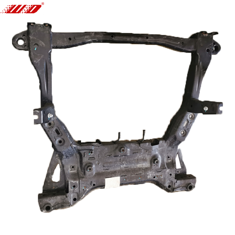
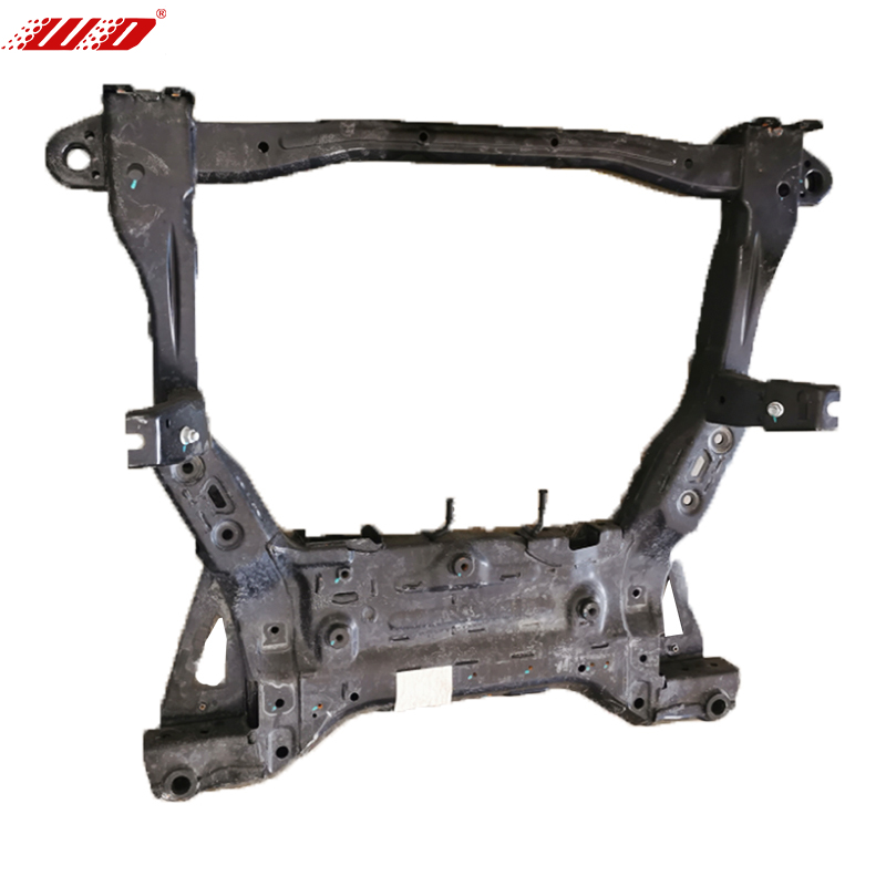
The front axle components do not mount directly to the unibody; they attach to a detachable front subframe that spreads suspension loads across a wider area of the chassis. This subframe, fabricated from high-strength steel pressings welded into a rigid assembly, also serves as the mounting point for the front electric drive unit and the steering rack. The subframe's mounting bushings isolate it from the chassis to reduce road noise transmission, but these same bushings degrade over time. When a subframe bushing collapses or tears, the entire front axle assembly shifts slightly under load, producing vague steering response and a sensation that the vehicle wanders or requires constant small corrections to maintain a straight line on the highway.
Subframe alignment is a frequently overlooked step during front axle repairs. The subframe-to-chassis bolts pass through slightly oversized holes that allow for manufacturing tolerance, and the subframe must be positioned using alignment dowels or a fixture before the bolts are torqued. If the subframe is reinstalled without this alignment step, the steering rack center position shifts relative to the suspension, resulting in an off-center steering wheel that no amount of tie rod adjustment can fully correct without introducing a side-to-side turning radius asymmetry. The correct procedure is to loosely install all subframe bolts, insert the alignment pins through the designated reference holes, torque the bolts to specification, and only then proceed with wheel alignment.
Diagnosing Noise, Vibration, and Handling Complaints
Front axle noise diagnosis follows a logical decision tree based on the conditions under which the symptom appears. A hum that increases with road speed and does not change with gear selection or whether the electric drive unit is under load points conclusively to a wheel bearing. A click that occurs only during tight turns at low speed points to an outer CV joint. A clunk during brake application or when transitioning from acceleration to deceleration suggests a worn control arm bushing or loose subframe bolt. These diagnostic rules are highly reliable and allow the source of a complaint to be narrowed down before the vehicle is even lifted on a hoist.
Vibration felt through the steering wheel is a more complex symptom because it can originate from a bent wheel rim, an out-of-balance tire, a failing inner CV joint, or a worn tie rod end allowing wheel shimmy. The diagnostic separation is accomplished by noting the speed at which the vibration occurs. A tire balance issue typically appears as a narrow-band vibration between 90 and 110 km/h and diminishes above or below that range. A CV joint vibration is load-dependent and intensifies under acceleration, diminishing when coasting. A tie rod end vibration is speed-independent but road-surface-dependent, appearing on rough pavement and disappearing on smooth asphalt. Systematically noting these conditions during a test drive eliminates guesswork and prevents the wasteful replacement of components that are not the root cause of the complaint.